
Case: Voltaic Fortis 1000 – Power Reimagined, From the Blueprint Up
1. Product Sketch: Conceptualizing the Core – The Architecture of Power
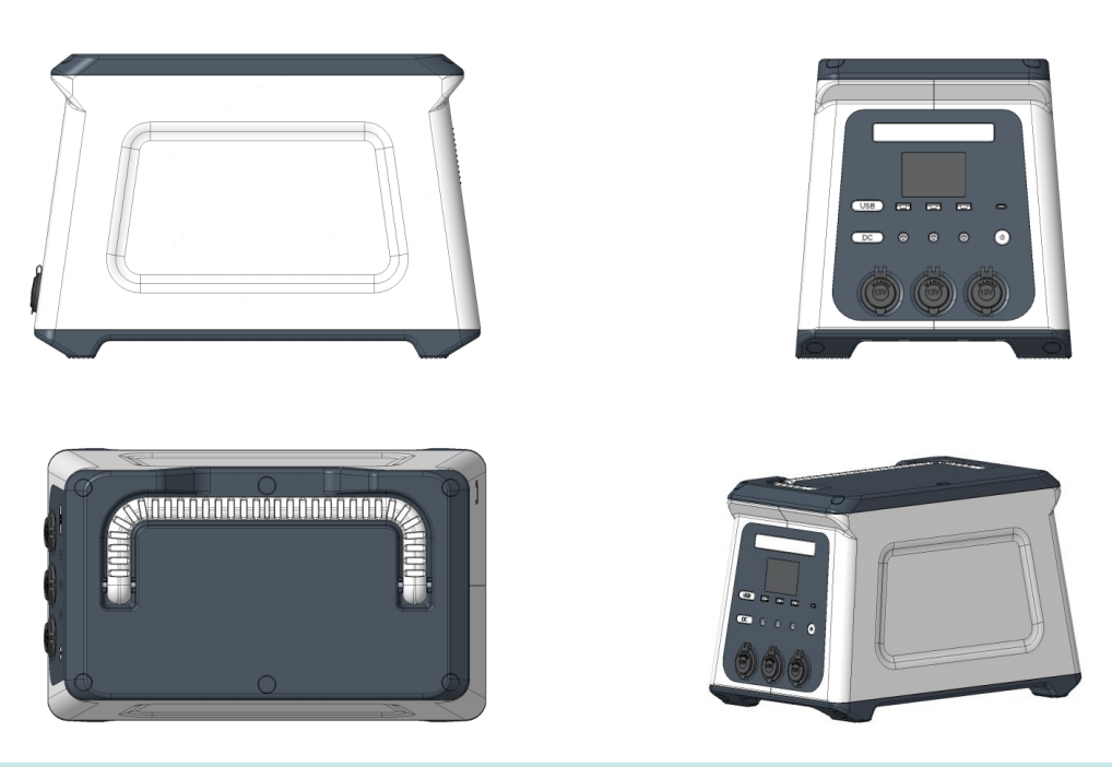
In the world of outdoor power, true innovation begins not on a workbench, but on a digital canvas. The Voltaic Fortis 1000 was born from this principle. The "Product Sketch" phase is where we move beyond a simple box with outlets; it's where we define the very soul and form of the power station. Our goal was audacious: to create the most powerful, reliable, and user-friendly portable energy source without compromising on portability or safety. This required a radical rethinking of internal architecture from the ground up, all within a sophisticated 3D modeling environment.
Using state-of-the-art 3D CAD software, our engineers and designers collaborated in a virtual space to block out the fundamental architecture. This stage was not about details; it was about proportions, balance, and core system integration. We meticulously positioned the three most critical and voluminous components—the Lithium Iron Phosphate (LiFePO4) battery cell array, the pure sine wave inverter, and the battery management system (BMS)—in a 3D space to achieve optimal weight distribution. A central, low-center-of-gravity design was paramount for stability on uneven ground. Simultaneously, we sketched the thermal management system, mapping the primary airflow pathways that would later become an advanced cooling solution. Every curve and angle of the external shell was initially drafted in 3D to serve a purpose: to protect the sensitive electronics within, to provide intuitive user interaction, and to create an iconic, rugged aesthetic that speaks of reliability. This digital blueprint became the foundational DNA of the Voltaic Fortis 1000, ensuring that every subsequent design decision would contribute to a harmonious and supremely functional whole.
*Table: Phase 1 - Product Sketch Design Objectives & Outcomes*
| Design Objective | 3D Design Approach | Outcome for the Voltaic Fortis 1000 |
|---|---|---|
| Optimal Internal Layout | Virtual placement and rearrangement of major components (battery, inverter, BMS) to balance weight and minimize internal wiring. | A stable, low-center-of-gravity "Tri-Core" architecture that prevents tipping and simplifies assembly, enhancing reliability. |
| Ergonomic Portability | 3D sculpting of the chassis around the internal components, focusing on handle placement and overall weight distribution. | A centrally mounted, reinforced steel handle and rounded corners that make lifting and carrying the 30lb unit surprisingly manageable. |
| Thermal Management Pathway | Initial 3D mapping of air intake and exhaust channels based on the heat profile of core components. | The foundational layout for the "CycloneFlow" dual-fan cooling system, ensuring heat is efficiently drawn away from critical parts. |
| User Interface (UI) Placement | Virtual reality (VR) mockups to test the visibility and accessibility of the display and ports from multiple angles. | A 15-degree angled top panel that brings all ports and the brilliant LCD screen into clear view, whether on the ground or a table. |
2. Detail Design: Engineering Precision – The Digital Masterpiece Comes to Life
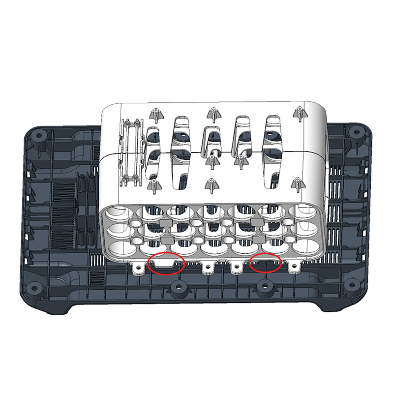
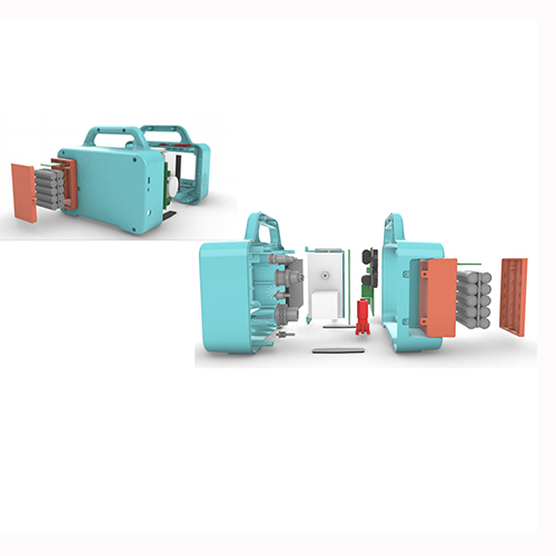
With the architectural blueprint approved, we plunged into the "Detail Design" phase. This is where our 3D model transformed from a concept into a hyper-realistic, fully engineered digital prototype. Every single component, down to the smallest capacitor, resistor, and USB port, was meticulously modeled and placed within the virtual chassis. This phase is the heart of our engineering process, where we achieve synergy between electrical brilliance and mechanical robustness.
We performed virtual stress analysis on the 3D models of the custom-designed aluminum heatsinks for the inverter and BMS, optimizing their fin density and surface area for maximum heat dissipation before a single prototype was milled. The complex multi-layer PCB (printed circuit board) was designed in 3D to ensure a perfect fit and to avoid interference with the structural ribs of the housing. Furthermore, we simulated the assembly process digitally, ensuring that every wire harness had adequate slack and was routed through cleverly designed channels to avoid pinching or wear from vibration—a critical factor for a product designed for the outdoors. The ports were not just placed; they were tested in the 3D model for ease of access, even with bulky outdoor gloves on. The reinforced ABS+PC shell was digitally sculpted with integrated impact-resistant ribs and precisely calculated wall thicknesses to shave off grams without compromising an ounce of protection. This obsessive attention to detail in the virtual world is what allows us to guarantee the legendary reliability of the Voltaic Fortis 1000. We dont just hope it will work; we have proven it will, through billions of digital data points.
*Table: Phase 2 - Detail Design: Virtual Component & System Integration*
| Component / System | 3D Detail Design & Engineering Process | Performance Advantage |
|---|---|---|
| UniBody Chassis with Internal Cage | The outer shell and an internal structural cage were modeled as a single unit. FEA (Finite Element Analysis) simulated drops from 1m onto concrete. | A monocoque design that distributes impact energy across the entire body, protecting the sensitive battery and electronics from shocks and vibrations. |
| "CycloneFlow" Active Cooling System | CFD (Computational Fluid Dynamics) analysis optimized the fan placement, vent shapes, and internal ducting for maximum airflow and minimal acoustic noise. | Dual silent fans (sub-40dB) that only activate under high load, pulling cool air in and expelling heat efficiently, preventing performance throttling. |
| Multi-Layer PCB & BMS Integration | The board was designed in 3D to fit perfectly within its allocated space, with connectors positioned to minimize wire length and reduce electronic noise. | A clean, efficient layout that enhances signal integrity, reduces energy loss, and allows the advanced BMS to precisely monitor and protect every cell. |
| Port Cluster Layout | 3D collision detection ensured no two plugs could interfere. Ergonomic simulation validated the spacing for simultaneous use of large adapters. | Perfectly spaced AC, DC, and USB-C ports (including two PD 100W) that can all be used at once without any awkward crowding or plug conflicts. |
3. Structural Design: The Virtual Torture Test – Validating Rugged Reliability
The final phase of our 3D design journey is where we prove the Fortis 1000's mettle against the brutal realities of the outdoors. The "Structural Design" phase is our digital proving grounds, a virtual torture chamber where we subject the complete assembly to extreme simulated stresses that far exceed normal use cases. This process transforms our design from a theoretical model into a product whose durability is a mathematical certainty.
Using sophisticated simulation suites, we applied the force of a 1.5-meter drop onto every possible corner and face of the virtual unit onto a rocky surface, analyzing stress concentrations and material deformation. We ran prolonged vibration analysis. the unit being driven thousands of miles on rough, corrugated dirt roads, identifying potential points of fatigue for solder joints and internal connections. Thermal runaway simulations were critical; we modeled worst-case scenario failures to ensure the battery enclosure and vents would contain and safely vent pressure, guaranteeing absolute safety. We even simulated environmental factors like driving rain and blowing dust, testing the integrity of seals and gaskets designed into the 3D model around the fan vents and port panel. This data-driven approach allowed us to make critical last-minute enhancements, like adding a minuscule but crucial reinforcing rib near the AC outlets or specifying a slightly more flexible rubber compound for the cable pass-through cover. By solving these problems in the digital realm, we eliminate them in the physical world, ensuring that when you take the Voltaic Fortis 1000 deep into the backcountry, its performance is the one thing you never have to worry about.
*Table: Phase 3 - Structural Design: Virtual Testing & Validation*
| Virtual Test Protocol | Simulation Parameters | Design Outcome & Validation |
|---|---|---|
| Multi-Angular Drop Test | Simulated 1.5m drops onto all 6 primary faces and 8 corners onto a rigid surface. | Redesigned the corners with internal "shock-absorbing" ribs and added a shock-dampening buffer between the battery pack and the outer shell. |
| Vibration & Fatigue Analysis | Applied real-world data from off-road vehicle vibrations for the equivalent of 1000 hours of driving. | Added strategic spot-welding points on the internal cage and specified anti-vibration lockers for critical electrical connectors. |
| IP Rating Validation (Ingress Protection) | CFD and particle flow analysis simulated exposure to blowing dust and water jets from all directions. | Redesigned the fan vent grilles to be 30% smaller and added a labyrinthine channel system to achieve a validated IP54 rating (dust and water resistant). |
| Extreme Thermal Load Testing | Simulated maximum inverter load (2000W surge) in a 45°C (113°F) ambient environment. | The CFD-guided "CycloneFlow" system was proven to keep internal components 20°C cooler than critical thresholds, preventing shutdown. |